Table of Contents
Raspberry PI Zero W
Initial SD card setup:
- Add to
cmdline.txtto enable Ethernet-over-USB:
modules-load=dwc2,g_ether - Create empty file
sshto start SSH server automatically
Initial server setup:
- Install x11vnc:
# apt-get install x11vnc
$ x11vnc -storepasswd
# echo 'su -l -c "x11vnc -rfbauth /home/pi/.vnc/passwd" pi'
- Other packages:
apt-get install vim tmux
Arduino


- People counter for ESP32 based on distance sensor.
 When selecting ATmega328 vs ESP8266 based solution, consider that ATmega328 would need 5V sensors, but ESP8266 would need 3-to-5V step-up when controlling LEDs.
ESP8266 has D3 / GPIO0 and D4 / GPIO2 10k pull-up + D8 / GPIO15 10k pull-down resistors, see LOLIN D1 mini description.
| Name | Price | CPU | CPU clock | Flash | SRAM / PSRAM | Networking | Power | Interface | PWM | DAC | Notes |
|---|---|---|---|---|---|---|---|---|---|---|---|
| Arduino Nano v3.0 | €3.60 + €0.92 = €4.52 | ATmega328P | 16Mhz | 32KB | 2KB |  shield costs €2.51 + €0.67 = €3.18 shield costs €2.51 + €0.67 = €3.18 | 5..12V | MiniUSB |  | | |
| LoLin NodeMCU V3 | €1.89 + €0.88 = €2.77 | ESP8266 | 80MHz | 4MB | 64KB | 2.4GHz WiFi 802.11 b/g/n | 3.3..12V (e.g. 3.7V LiIon) | MicroUSB | | | |
| Wemos D1 mini V1 | €1.76 + €0.66 = €2.42 | ESP8266 | 80MHz | 4MB | 64KB | 2.4GHz WiFi 802.11 b/g/n | 3.3..12V (e.g. 3.7V LiIon) | MicroUSB | | | |
| Wemos D1 mini Pro V1.1 | €2.67 + €0.65 = €3.32 | ESP8266 | 80MHz | 16MB | 128KB | 2.4GHz WiFi 802.11 b/g/n | 3.3..12V (e.g. 3.7V LiIon) | MicroUSB | | | |
| Wemos ESP32-S2 Mini | €2.69 | 240MHz | 4MB | 320KB / 2MB | 2.4GHz WiFi 802.11 b/g/n | 5V (USB) | USB-C | | 2× (GPIO17+18) | ||
| ESP32-C3 SuperMini | €2.39 | ESP32C3FN4 | 160MHz | 4MB | 400KB | 2.4GHz WiFi 802.11 b/g/n, Bluetooth 5.0 | 5V (USB) | USB-C | | 4× | 43µA in deep sleep, 22.5×18 mm |
| ESP32-C6 | €12.45 | ESP32C6FH4 | 160MHz | 4MB | 512KB HP + 16KB LP | Wi-Fi 6 (2.4 GHz), Bluetooth 5.0 (LE), Thread (802.15.4) | 5V (USB) | USB-C | | 7× | 26×18 mm |
Check:
CH341SER.ZIP).
ESP
- ESPHome is a tool which reads in a YAML configuration file (just like Home Assistant) and creates a custom firmware binary. The tool also has many helpers that simplify flashing devices (uploading the new binary file) and aim to make managing your ESP boards as simple as possible.
- Tasmota – alternative firmware for ESP-based IOT devices that adds extra functionality to them
- Fixin’ a Glitchin’ ESP8266 (or How to use two FNB58 as a Dual Channel Oscilloscope) – adding the 100uf capacitor on 3.3V rail significantly improves voltage and current response thus adding to stability, another step is to replace the default (underpowered) linear regulator with TPS73633 or RT9013.
LED strips
")


- NeoPixelBus – a library to control one wire protocol RGB and RGBW LEDs like SK6812, WS2811, WS2812 and WS2813
-
- Answers to the most common DIY LED questions – 1000 LEDs on one PIN, 35mA per LED, max 60 cm data line (can be boosted up to 40 meters if using sacrificial LED)
-
-
Smart meter
 pinout")


Challenges:
ESPHome installation:
- Install ESPHome from docker and open http://localhost:6052/:
# docker run --rm --net=host --privileged -v "$(pwd):/config" esphome/esphome
- Paste the following configuration then press Install → Manual Download which will compile the firmware and offer
smart_meter.binfile which should be saved locally:esphome: name: smart_meter friendly_name: "Smart meter" esp8266: board: d1_mini # For complete list check https://registry.platformio.org/platforms/platformio/espressif8266/boards logger: hardware_uart: UART1 # D4 on D1 mini tx_buffer_size: 4096 ota: - platform: esphome password: "<replace password>" api: # Expose API for Home Assistant integration wifi: ssid: "<replace network>" password: "<replace password>" substitutions: mqtt_prefix: "smart_meter" mqtt: broker: 192.168.1.10 username: "<replace user>" password: "<replace password>" topic_prefix: "${mqtt_prefix}" log_topic: "${mqtt_prefix}/logs" keepalive: 300s # Otherwise MQTT client reconnects every 15 seconds uart: rx_pin: GPIO3 # RX pin on D1 mini baud_rate: 115200 rx_buffer_size: 1500 # A bit bigger than P1 message size sensor: - platform: dsmr power_delivered: name: "Power Currently Consumed" state_topic: "${mqtt_prefix}/power_consumed" power_returned: name: "Power Currently Produced" state_topic: "${mqtt_prefix}/power_returned" voltage_l1: name: "Voltage L1" state_topic: "${mqtt_prefix}/voltage_l1" current_l1: name: "Current L1" state_topic: "${mqtt_prefix}/current_l1" energy_delivered_tariff1: name: "Total Energy Consumed Tariff 1" state_topic: "${mqtt_prefix}/energy_consumed_tariff1" energy_delivered_tariff2: name: "Total Energy Consumed Tariff 2" state_topic: "${mqtt_prefix}/energy_consumed_tariff2" energy_returned_tariff1: name: "Total Energy Produced Tariff 1" state_topic: "${mqtt_prefix}/energy_returned_tariff1" energy_returned_tariff2: name: "Total Energy Produced Tariff 2" state_topic: "${mqtt_prefix}/energy_returned_tariff2"
- Open https://web.esphome.io/ in Chrome, press Connect and choose the appropriate COM port ESP8266 is connected to. Press Install → Choose file, select previously downloaded
smart_meter.binand press Install. - After 1st installation it is possible to update firmware wirelessly using OTA (choose Wirelessly). ESPHome installator will automatically display logs using API connection.
- Alternatively one can monitor logs using
mosquitto_sub -v -t 'smart_meter/#' -u aaa -P bbb
Network:

- CustomSoftwareSerial library supports many modes including 7E1 and 8N1.
- Similar problem here
Power saving:
Sensors
- Датчики и микроконтроллеры: климат-контроль – описывает датчики температуры, влажности, давления
- Сенсорный выключатель – capacitive digital touch sensor / switch review


 vs BMP280 (pressure and temperature)")
Vibration
Curtain
Temperature
Infrared thermograph / temperature sensor
Climate control / CO₂
Oximeter / pulsometer
Door bell
Measuring current:
- Measuring Current with Microcontrollers: 7 Sensors tested – with resistors: MAX4080, INA169, INA219; with Hall sensors: ACS712, ACS758, WCS1800; Coulomb counter: LTC4150
- INA219 Tutorial for Arduino, ESP8266 and ESP32 – max 26V / 3A, I²C

- Схема детектора тока на оптопаре:
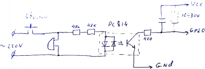
В сумме резисторы определяют ток протекающий через светодиод. Чем он меньше, тем больше сопротивление перехода коллектор эмитер транзистора. Поскольку транзистор работает на высокоомный вход GPIO, то, думаю, конденсатор на 5-10 мкф + резистор подтяжки в пределах 10-20 кОм хватит. Наверно можно отойти от рекомендаций даташита и ограничить ток светодиодов парой милиампер (резисторы меньше греться будут) – тогда можно поставить два резистора в пределах 50 кОм.
Для вычисления мощности резисторов берём закон Ома и считаем. Как на постоянном токе, считаем действующие значения тока и напряжения. 220В у нас падает на двух последовательных резисторах и диоде. Ну на диоде упасть больше 2В в принципе не может (как и меньше тоже) – им пренебрегаем – и считаем ток в цепи 220В/(50+50) кОм = 2.2 мА. Мощность рассеиваемая на резисторе считаем по формуле I×I×R = 2мА×2мА×50кОм=0.24 Вт плюс на втором резисторе ещё 0.24Вт, т.е всего рассеивается 0.48Вт чистым теплом. Поверьте это не мало. Один резистор в 100 кОм должен был бы рассеять почти 0.5Вт тепла. Хотя для варианта с детекцией дверного звонка этот кратковременный нагрев можно не считать проблемой.


Battery voltage measurement
It is possible to measure battery voltage using build-in ADC. Voltage on ADC internal ESP PIN can be calculated using this formula (voltage divider):
To measure voltage 4.2V LiIon battery one needs 100 kΩ resistor.
| Name | Parameters | Voltage at ADC internal input (should be 1V or less) | Quiescent current | Power loss on divider |
|---|---|---|---|---|
| Standard power voltage on build-in divider (no additional resistor is needed) |
|
|||
| 16.8 V (4S) battery voltage: additional resistor 1.3 MΩ is needed, which including the build-in 220 kΩ resistor: |
|
Check also:
Logical converter


USB-UART converter


CH340E:
Controlling the power
Using relay

See also:
Using MOSFET e.g. IRLB3034PbF
- Drain-to-Source Breakdown Voltage (V(BR)DSS): 40V
- Gate Threshold Voltage (VGS(th): 1.0-2.5V
- Static Drain-to-Source On-Resistance (RDS(on)): 1.6-2.0 mΩ
- Рассеиваемая мощность при токе 5A: Pdis = 2mΩ × (5A)2 = 0.002Ω × 25A = 0.05W → температура корпуса транзистора будет RθJA × Pdis + Croom = 0.05W × 62°C/W + 25°C = 27.1°C
See also:
- Arduino + IRLB3034PbF example (via 100Ω resistor)
Using Solid State Relays (SSR)
")


")
See also:
Using dedicated controller + MOSFET
- Автоматический переключатель питания на микросхеме LTC4412.
Dimmer
Other automations
FAQ
Arduino Nano uploading gives error: avrdude: stk500_recv(): programmer is not responding
Tools → Processor → ATmega328P (Old Bootloader).
Arduino Nano build-in LED conflicts with Ethernet shield
Alternative way to flash Wemos D1

Connect the following pins between NodeMCU and Wemos D1:
- RX → RX
- TX → TX
- D3 → D3
- RST → RST
- 3.3V → 3.3V
- GND → GND
- EN → GND
With USB-TTL converter:
- RX → TX
- TX → RX
- 3.3V → 3.3V
- GND → GND
- D3 → GND (GPIO0 should be grounded when ESP is starting)
NodeMCU v3 (LoLin) built-in LED features
 LEDs operate in “inverted” mode, with regard to the pin levels – when the pin is LOW, the LED is on.
Runnning pinMode(1, OUTPUT); breaks serial communication (when doing Serial.println("..."); nothing is printed) because pin 1 and 3 are reserved for TX/RX.
Builtin LED on NodeMCU v3 (LoLin) is on D4 (pin 2) i.e. use pinMode(2, OUTPUT);